|
 |
|
 |
|
| Author |
Message |
Robotprops
Community Member
Joined: 11 Apr 2010
Posts: 280
Location: Vancouver, B.C.
|
 Posted: Mon May 16, 2011 1:12 am Post subject: Origin of the sight rod Posted: Mon May 16, 2011 1:12 am Post subject: Origin of the sight rod |
 |
|
Mspaw's recent works of wonder have me asking if the original sight rod origins were ever determined. A fellow fan once told me it was an antique pen of some sort but I've never had that confirmed.
Any thoughts? |
|
| Back to top |
|
|
|
|
 |
|
 |
|
|
|
|
| Author |
Message |
Vader
Community Member

Joined: 19 Feb 2011
Posts: 267
Location: Sweden
|
| Posted: Mon May 16, 2011 2:06 am Post subject: |
|
|
Last I checked it hadn't been positively identified, but it seems to be generally recognised to have the "look and feel" of a period fine mechanic's tool of some sort, like a screwdriver handle or something in that vein.
_________________
26354 |
|
| Back to top |
|
|
|
|
|
|
|
|
|
|
|
| Author |
Message |
Robotprops
Community Member
Joined: 11 Apr 2010
Posts: 280
Location: Vancouver, B.C.
|
| Posted: Mon May 16, 2011 2:39 am Post subject: |
|
|
| Micro driver handle seems plausible. I have a jewelers driver that suits the style. |
|
| Back to top |
|
|
|
|
|
|
|
|
|
|
|
| Author |
Message |
Bwood
Community Member
Joined: 20 Sep 2009
Posts: 843
|
|
| Back to top |
|
|
|
|
|
|
|
|
|
|
|
| Author |
Message |
racprops
Community Member

Joined: 30 Oct 2006
Posts: 2450
Location: Phoenix AZ
|
| Posted: Mon May 16, 2011 11:19 am Post subject: |
|
|
I have always held to the idea it is a jewelers screw driver.
I have had some that looked very much like it, remove the shaft and it has the same sized hole.
A little milling and you have got the cut outs and as the front cut is a little rough, it looks to have been cut into the shaft and not made with it.
Add the knelled end shaft and you got it.
Rich
_________________
I never have enough time to do all I want to do! |
|
| Back to top |
|
|
|
|
|
|
|
|
|
|
|
| Author |
Message |
andy
Community Guide

Joined: 01 Nov 2006
Posts: 6237
Location: Rochester, NY
|
| Posted: Mon May 16, 2011 11:28 am Post subject: |
|
|
Rich,
Please post pics of the Jeweler's screw driver you have that is similar. I have looked and not found one yet that is close. In most cases they are much smaller too. They do share a couple characteristics, but they are also things that are standard machinist details for making tools and such for purely functional items. Pin vices too that I have seen have been too large. I have a long list of items I have seen that have similarities, but nothing yet that shares more than a couple characteristics, and usually has other things that keep it from not working. It has been a long time since we speculated on this piece, and I would love to see some new ideas about it, with pictures and comparisons of others theories.
Andy |
|
| Back to top |
|
|
|
|
|
|
|
|
|
|
|
| Author |
Message |
racprops
Community Member
Joined: 30 Oct 2006
Posts: 2450
Location: Phoenix AZ
|
| Posted: Mon May 16, 2011 12:10 pm Post subject: |
|
|
Had as in the past...
40 years ago.
Rich
_________________
I never have enough time to do all I want to do! |
|
| Back to top |
|
|
|
|
|
|
|
|
|
|
|
| Author |
Message |
andy
Community Guide
Joined: 01 Nov 2006
Posts: 6237
Location: Rochester, NY
|
| Posted: Mon May 16, 2011 2:22 pm Post subject: |
|
|
Had what?
Andy |
|
| Back to top |
|
|
|
|
|
|
|
|
|
|
|
| Author |
Message |
racprops
Community Member
Joined: 30 Oct 2006
Posts: 2450
Location: Phoenix AZ
|
| Posted: Mon May 16, 2011 2:38 pm Post subject: |
|
|
I had a jewelers screw driver that was a large one like the one used on the gun.
Rich
_________________
I never have enough time to do all I want to do! |
|
| Back to top |
|
|
|
|
|
|
|
|
|
|
|
| Author |
Message |
Vader
Community Member
Joined: 19 Feb 2011
Posts: 267
Location: Sweden
|
| Posted: Mon May 16, 2011 5:39 pm Post subject: |
|
|
I'm with Rich on this one. The screwdriver set here (click image for larger view) is a typical example of how precision screw drivers have tended to look for at least four decades. The only thing wrong with them is that the knurls are of the wrong kind, and in the wrong place (these have better knurls, but otherwise not very useful as an example).
- Removing the blade and the revolving butt plate is a snap.
- The size issue is moot — as you can see, there is a selection, and one of them is bound to be more or less correct.
- It is certainly conceivable that a model of similar precision drivers would have existed at some time with a flat main part and knurls only at the base, as on the sight rod. Perhaps even complete with the grooves seen on the rod?
- And even had this not been the case, I think it would actually be quite simple to manufacture a close-to correct rod out of one of these — first fix it in a lathe, turn the grooved handle flat and use a knurling tool on the base, then mill the grooves, and you're done!
As andy noted, pin vises tend to be much too large.
To me, the similarities between precision screwdrivers as I've come to know them and the sight rod are simply too large to ignore...
_________________
26354 |
|
| Back to top |
|
|
|
|
|
|
|
|
|
|
|
| Author |
Message |
andy
Community Guide
Joined: 01 Nov 2006
Posts: 6237
Location: Rochester, NY
|
| Posted: Mon May 16, 2011 6:22 pm Post subject: |
|
|
I am not convinced that it can be, or not be a screw driver, but there are still way too many things which work against it being one. The knurled part should be in the center. The butt/end cap looks like it is a separate part, which would be closer in design to a mechanical pen or vise. It could even be a part from something else all together and be a marriage of two or more parts.
Sure, they could have altered the screw driver by grinding off the center ribbing, and then milling the larger grooves, but this makes no sense to me. The whole concept of greeblies is to add found parts that you don't need to modify too much in order to save time in fabrication. It would almost been as easy to totally create something from scratch to look more interesting, or just dig deeper into the parts bin to find something else that would work without modification. especially since I think it is a lot harder to remove a screw driver shaft from one of these things, because they have to be permanently seated in them to prevent slipping, and give control. A skilled machinist could have cut a new one out of a piece if tubing in a manner of minutes without having to spend any time removing the shaft and then making all the other alterations.
Other things that seems more likely is that it is just an uncommon part or one that may have been mostly or completely obscured inside of a larger machine, so finding pictures of it would be close to impossible. Also the shop may have made it's own tools and parts for projects, and this one could have been a discard that was never used, or finished, explaining why the grooves are not milled on all sides of the rod. I find all these theories to be pretty much unlikely as well, but not much more than the screw driver theory. I think until we get a better clue, we are still just wildly speculating here.
Andy |
|
| Back to top |
|
|
|
|
|
|
|
|
|
|
|
| Author |
Message |
racprops
Community Member
Joined: 30 Oct 2006
Posts: 2450
Location: Phoenix AZ
|
| Posted: Mon May 16, 2011 7:01 pm Post subject: |
|
|
I more or less agree with all Andy said.
I DO think a screw driver was the Inspiration of the part.
I agree the removal of the main shaft whould be hard.
So I think it was machined as a new part following a know part, the jewelers screw driver.
Rich
_________________
I never have enough time to do all I want to do! |
|
| Back to top |
|
|
|
|
|
|
|
|
|
|
|
| Author |
Message |
andy
Community Guide
Joined: 01 Nov 2006
Posts: 6237
Location: Rochester, NY
|
| Posted: Mon May 16, 2011 8:47 pm Post subject: |
|
|
Here are the pics vader was talking about for easier reference...


There is no doubt that front part of the screwdriver is almost dead on to what we see on the LED sight rod, but there are countless other tools and such that have the same detail.
Andy |
|
| Back to top |
|
|
|
|
|
|
|
|
|
|
|
| Author |
Message |
andy
Community Guide
Joined: 01 Nov 2006
Posts: 6237
Location: Rochester, NY
|
| Posted: Mon May 16, 2011 9:00 pm Post subject: |
|
|
Here is a picture of some vintage machinist's scribes, that have some in structure with the hollow shaft, pointed front, and knurled back end for tightening.
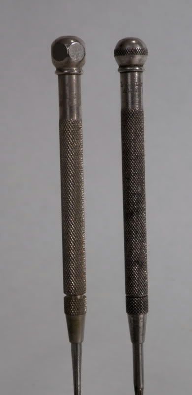
Still these look very different from the sight rod and screw driver, they have a lot more design variation over different versions than the screwdrivers.

Andy |
|
| Back to top |
|
|
|
|
|
|
|
|
|
|
|
| Author |
Message |
OUTLAW
Community Member
Joined: 05 Mar 2011
Posts: 31
|
| Posted: Tue May 17, 2011 1:05 am Post subject: Question. |
|
|
So who was the original blaster prop builder ?
Have I missed that info on here as I don´t seem to have seen any mentions, was it one guy or a team ?
Surely there must have been an interview or questions asked at some stage.
Would be very interesting to know what he or they were thinking, where the influences came from and how it all came together.
I´ve read about and seen the OG concept blaster and also read that Ridley saw the Bulldog and Steyr parts and wanted these using but nothing more. |
|
| Back to top |
|
|
|
|
|
|
|
|
|
|
|
| Author |
Message |
racprops
Community Member
Joined: 30 Oct 2006
Posts: 2450
Location: Phoenix AZ
|
| Posted: Tue May 17, 2011 3:54 am Post subject: |
|
|
At one time early in the work up of the Blaster, Phil and I got a hold of the prop master on the film.
Well the one whose name remained on the film.
It is my understanding a few came and were let go during the filming.
In hind sight I now feel he did not remember details correctly, as he had said the two holes I found in the stunt prop ammo housing was used to turn on and off the LEDs, (a toothpick switch, a small switch behind the wall operated by pushing something though the holes, like a tooth pick,) We now know about the switch in the ammo clip between the LEDs.
He also said the side rod was added because there was a ugly overhang of the Steyr receivers cut out to clear the cylinder and the side cover, so the rod was added to fill that. In building the model I saw that and figured that was why it was added.
He would not give us the full name of the gun smith who did all the work only that his first name was Fred, or Jim. Somewhere I got a hint he might have passed.
Someone might try recontacting the named prop master and find out any others whom worked on the film and perhaps more can be learned.
I still feel that as the side rod closely matches the size and front detail of a jeweler’s screw driver, that such could have been considered as the gap filling device, but for the desire for working LEDs, which would make machining a hollow unit a must, and with the plan sides the four mill cuts were added for detailing.
After all this is what was done with the main bolt, a long mill cut was added to the bolt where it showed though the injector port.
My 2 cents worth.
Rich
_________________
I never have enough time to do all I want to do!
Last edited by racprops on Tue May 17, 2011 11:14 am; edited 1 time in total |
|
| Back to top |
|
|
|
|
|
|
|
|
|
|
|
| Author |
Message |
OUTLAW
Community Member
Joined: 05 Mar 2011
Posts: 31
|
| Posted: Tue May 17, 2011 10:50 am Post subject: |
|
|
| Thanks for the info, very interesting. |
|
| Back to top |
|
|
|
|
|
|
|
|
|
|
|
| Author |
Message |
andy
Community Guide
Joined: 01 Nov 2006
Posts: 6237
Location: Rochester, NY
|
| Posted: Tue May 17, 2011 2:32 pm Post subject: |
|
|
Here is one of the original threads about the "sight rod"...
http://propsummit.com/viewtopic.php?t=838
It has some great pictures in it, as well as a bunch of the theories we have already explored. Recommended reading on this topic for sure.
Andy |
|
| Back to top |
|
|
|
|
|
|
|
|
|
|
|
| Author |
Message |
andy
Community Guide
Joined: 01 Nov 2006
Posts: 6237
Location: Rochester, NY
|
| Posted: Tue May 17, 2011 5:13 pm Post subject: |
|
|
Several things I have thought about in the past is that the grooves in the center part of the rod may have been there because an outer rubber or similar wrapping may have covered the center part, and the grooves were there to keep it from turning. They also could have been where the center shaft was drilled out to access the screws attaching it to the gun's cover, and even the wiring, and then puttied over and painted. Some more food for thought.
Andy |
|
| Back to top |
|
|
|
|
|
|
|
|
|
|
|
| Author |
Message |
DonParker
Community Member
Joined: 09 Jan 2009
Posts: 250
|
| Posted: Tue May 17, 2011 5:19 pm Post subject: |
|
|
If I were to make one out of the existing screwdrivers in
the above link, I would just chuck it in the lathe and turn
the knurl off. If you used the bigger drivers and did that,
you could then re-knurl it to the diamond pattern and
mill the indents with a ball endmill.
Don |
|
| Back to top |
|
|
|
|
|
|
|
|
|
|
|
|
You cannot post new topics in this forum
You cannot reply to topics in this forum
You cannot edit your posts in this forum
You cannot delete your posts in this forum
You cannot vote in polls in this forum
|
|
|
|
|
|
|
|