|
 |
|
 |
|
| Author |
Message |
joberg
Community Member
.jpg)
Joined: 06 Oct 2008
Posts: 9447
|
 Posted: Sun Sep 01, 2013 4:23 pm Post subject: Posted: Sun Sep 01, 2013 4:23 pm Post subject: |
 |
|
Looks mighty good Colin...I know, we tend to want to make it perfect and I understand your ways (I'm the same  ); keep up the good work ); keep up the good work  |
|
| Back to top |
|
|
|
|
 |
|
 |
|
|
|
|
| Author |
Message |
8th_Passenger
Community Member

Joined: 28 Nov 2009
Posts: 443
Location: Hertfordshire, UK
|
| Posted: Mon Sep 09, 2013 3:01 am Post subject: |
|
|
As I hoped I got my laser-cut parts at the end of last week. So over the weekend I started putting them together.
There is a certain amount of déjà Vu here so apologies for the repetition!
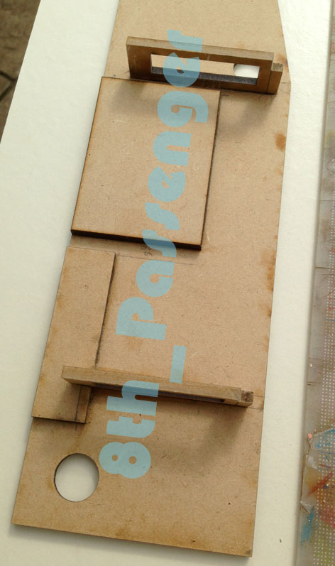
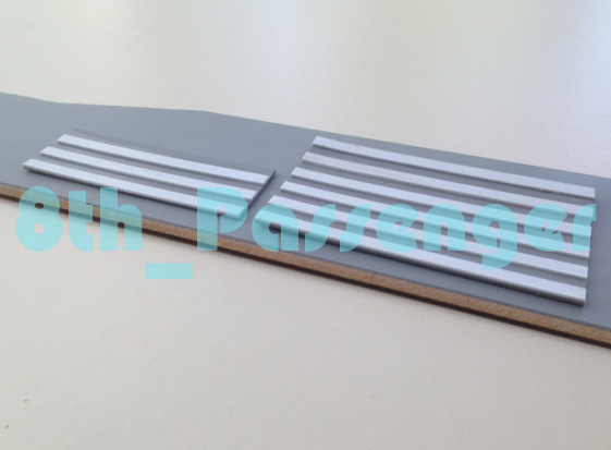
Here are the basic body parts with a few extra parts to help in construction.

The construction is very similar to page one of this thread. But it is different!
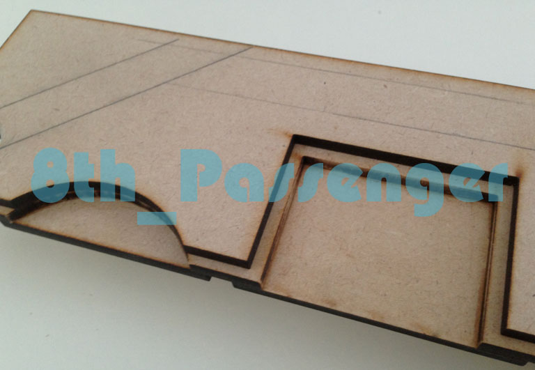
So I started off creating the recess' in the right side of the body by adding some MDF to the back of the panel. These recess' are to make it easier to turn the knobs on the scuba yoke I think. Once these were in place I glued the right side internal bulkheads in position.
Here's the step effect it will create once the final side body panel is on. I have to put a chamfer on the final panel before I can fit it.
Next I installed the front bulkhead along with the (front) end panel and (front) top panel.

The bolts in the front bulkhead will allow me to secure the emitter rods in position. I will cover this in more detail when I get there.
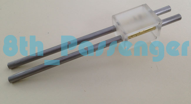
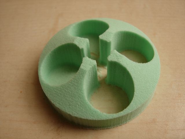
I had planned on shaping and drilling a block of 'material' to hold the emitter rods. But in the end I thought creating a laser cut structure would make it easier lining up the rods. Also I didn't have access to a pillar drill so laser cutting a structure made sense.
Laser Cut structure assembled with brass internal sleeves.
This photo show's the bottom rails of the body's internal structure which I machined up on a circular saw and finished off by hand. These create a shoulder for the internal steel structure to sit against.

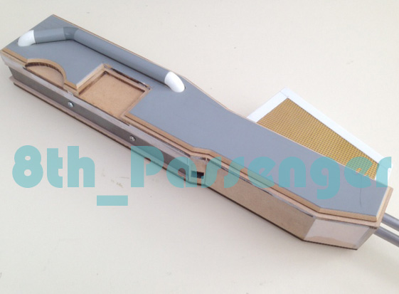
So here is an overview of where I'm at. Showing parts in their relative positions.

Here's the block of Jelutong I've cut for the top vent. The etched brass is from EMA/Plastruct. I'm going to clad this in ABS sheet.

I got my initial metal order too. I didn't want to go too mad just in case things weren't working out. Here is the steel hexagonal bar with the scuba tank attached.
So things are finally beginning to take shape!
Colin |
|
| Back to top |
|
|
|
|
|
|
|
|
|
|
|
| Author |
Message |
joberg
Community Member
Joined: 06 Oct 2008
Posts: 9447
|
| Posted: Mon Sep 09, 2013 6:17 pm Post subject: |
|
|
| Wow, beautiful prep work (so sharp)...love it to bits and eager to see the next episode |
|
| Back to top |
|
|
|
|
|
|
|
|
|
|
|
| Author |
Message |
SKIN JOB 66
Community Member

Joined: 16 Jan 2008
Posts: 2724
Location: FRANCE
|
| Posted: Tue Sep 10, 2013 5:23 pm Post subject: |
|
|
Same as JB, Colin I love the way you work... So perfectly planned and made, your progress pics and thoughts are always a real pleasure for the eye and mind !
Fred
_________________
THE FUTURE IS A THING OF THE PAST |
|
| Back to top |
|
|
|
|
|
|
|
|
|
|
|
| Author |
Message |
Mr Webber
Community Member

Joined: 13 Apr 2008
Posts: 1824
Location: Terra Australis
|
| Posted: Tue Sep 24, 2013 7:04 pm Post subject: |
|
|
Super detail, this ones gunna be the benchmark for sure.
_________________
Formerly offworld66 |
|
| Back to top |
|
|
|
|
|
|
|
|
|
|
|
| Author |
Message |
8th_Passenger
Community Member
Joined: 28 Nov 2009
Posts: 443
Location: Hertfordshire, UK
|
| Posted: Wed Sep 25, 2013 9:07 am Post subject: |
|
|
Thank you offworld66.
I hope I don't disappoint.
I will have another update in the next few days.
Colin |
|
| Back to top |
|
|
|
|
|
|
|
|
|
|
|
| Author |
Message |
joberg
Community Member
Joined: 06 Oct 2008
Posts: 9447
|
| Posted: Wed Sep 25, 2013 6:08 pm Post subject: |
|
|
Well Colin, so far your builds have been perfect as far as I'm concerned...so I'm sure that this one will be another success
I know, no pressure  |
|
| Back to top |
|
|
|
|
|
|
|
|
|
|
|
| Author |
Message |
8th_Passenger
Community Member
Joined: 28 Nov 2009
Posts: 443
Location: Hertfordshire, UK
|
| Posted: Thu Sep 26, 2013 5:55 am Post subject: |
|
|
Thanks Joberg.
Time for an update. The first of a few!
First off.
I've decided I have three options for the look of the top vent.
So here they are.
‘A’ - folded bent metal

The folded metal is on the unit Parker slams on the table after Dallas’ death. I could achieve this by folding some sheet aluminum to fit my former.
This style is also on the one which came up for auction recently from the collection of John Gorman.

Then
‘B’ - seamless side
.jpg)
This style is mostly seen on the flamethrower in the ‘white background’ publicity stills of Sigourney Weaver and on the mess table in some of the stills from the DVD and Blu Ray. It looks like one piece with no added detail apart from the strap plate. I could achieve this by vacuum forming over my Jelutong former.
Finally
‘C’ – Hybrid
This look is really an extension of ‘B’. In some shots there is a subtle step. Like an extra strip has been added. You can see it here in this photo of Yaphet Kotto.

And you can see the remains of it here on the Propstore one.
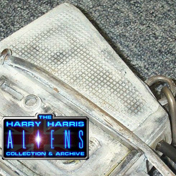
But I think what's happened here is some wires have been glued onto the outside of the vent casing.
Probably the wires for the igniter. You can see them in this photo.

As these have been replaced/changed, due to the heat maybe, they have pulled off the material strip following the side shape of the vent. This could be one of the reasons they are missing on the Propstore one. That and general wear and tear.
So which would be the definitive version?
I may try making a version of each and see which looks best.
The next instalments will be about the emitter options and more on the build.
Colin |
|
| Back to top |
|
|
|
|
|
|
|
|
|
|
|
| Author |
Message |
8th_Passenger
Community Member
Joined: 28 Nov 2009
Posts: 443
Location: Hertfordshire, UK
|
| Posted: Thu Sep 26, 2013 8:59 am Post subject: |
|
|
Okay round two!
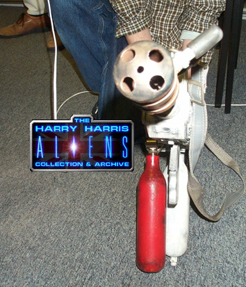
These are the two versions of the emitter.
'A' the machined.
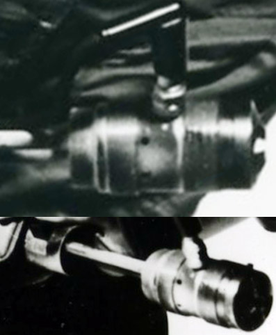
The 'A' version has a smooth transition into the end from the front ring. The five hole configuration in the front is connected by a cross (void).

Here’s a test I did a few years ago to illustrate how it looks.
Then there is
'B' the capped end.
The capped end ones are the ones that have been sold at auction.
Here they both are

The Propstore one has a definite capped end with five holes in the end.
The John Gorman auction one has a similar end but is smooth from the front ring. Like it’s all one piece (probably original!). And again this has the five holes.
So I'm under the impression that the cap on the Propstore is a replacement! Perhaps when the prop was decommissioned. Replaced in the style of the John Gorman one. Interestingly I think the Propstore one was originally owned by John Gorman. So that would make sense.
Also I can't find any screen used shots of the capped ones.
So I think I’ll go with the machined look emitter end.
Hope that all made sense?
Of course I may be wrong on all counts.
Colin |
|
| Back to top |
|
|
|
|
|
|
|
|
|
|
|
| Author |
Message |
8th_Passenger
Community Member
Joined: 28 Nov 2009
Posts: 443
Location: Hertfordshire, UK
|
| Posted: Thu Sep 26, 2013 10:54 am Post subject: |
|
|
Round three!
Returning to the build.
I wanted to ‘beef up’ the structure around the emitter rods because I didn't use a block like I had planned to.
So I sprayed the steel rods with some release agent then located them back into the brass sleeves in the laser cut structure. I then used epoxy glue to stick the mount in place.

Using some clay I temporarily plugged up any holes. Then using my steel cube with some packing tape applied I blocked up the opening. Again sealing with clay.

Next I poured fastcast into the voids to lock everything together.

When set I could remove the rods.

With this complete I moved back onto the side panels. The time had come to put the chamfer on the edges.
Setting up a makeshift router table I routed the chamfer.
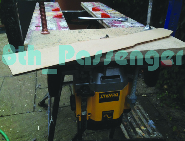

I need to take a bit more off. I was barely on the follow wheel so I need to double side some extra panels on (of the same shape) and go round again. I want to leave a bit of a flat on the bottom edge. But as it stands now its a bit too much.
I'd bought some EMA Bends and tube to work out this side pipe.


After I'd mocked it up and fitted it I wasn't happy. I thought it looked a bit chunky. Here it is with the detail panel missing!

So I decided to go smaller thus making it thinner. I bought the next two sizes down but chose the middle size. Here's a comparison.

I think it does improve it visually!
So I had to do some cutting and filling to get the new size in position. Luckily I'd made this decision before I'd cut the holes in the ABS sheet. I could just back fill the laser cut holes with some fastcast.
This is how it stands now.

I'm pretty happy with it at this point. Close enough.
I will replace the ABS tube with turned urethane model board so I can get better detail . I will then mould it and cast it.
Making slow progress but getting there.
Colin |
|
| Back to top |
|
|
|
|
|
|
|
|
|
|
|
| Author |
Message |
joberg
Community Member
Joined: 06 Oct 2008
Posts: 9447
|
| Posted: Thu Sep 26, 2013 5:55 pm Post subject: |
|
|
Love the build for sure  . For the emiter, I would go with the open end (looks nastier). As for the pipe, are you going to cut it in half so it can be against the body of the flame thrower? . For the emiter, I would go with the open end (looks nastier). As for the pipe, are you going to cut it in half so it can be against the body of the flame thrower? |
|
| Back to top |
|
|
|
|
|
|
|
|
|
|
|
| Author |
Message |
8th_Passenger
Community Member
Joined: 28 Nov 2009
Posts: 443
Location: Hertfordshire, UK
|
| Posted: Sat Sep 28, 2013 2:25 am Post subject: |
|
|
joberg wrote.
| Quote: | | As for the pipe, are you going to cut it in half so it can be against the body of the flame thrower? |
Joberg that's a good question. For a long time I thought it was half round or sunk half way into the side panel. But the more I look at the reference the more it looks like a full tube sitting on the surface. My original thought was to sink it in about 5mm. I still have this option and it would look pretty good. There are photo's which show the light 'wrapping' round the tube. This would suggest it's not half round.
I'll try find and post the best picture later.
Did you have any thoughts on which vent casing to go for?
Colin |
|
| Back to top |
|
|
|
|
|
|
|
|
|
|
|
| Author |
Message |
joberg
Community Member
Joined: 06 Oct 2008
Posts: 9447
|
| Posted: Sat Sep 28, 2013 7:47 pm Post subject: |
|
|
Colin, maybe I was a little "too much" with the suggestion of half a tube...let's just say that at least 1/4 is gone...unless you have access to pics I've never seen before
As for the vent, I would go with the "stepped" one; it adds a little detail to that whole piece. |
|
| Back to top |
|
|
|
|
|
|
|
|
|
|
|
| Author |
Message |
8th_Passenger
Community Member
Joined: 28 Nov 2009
Posts: 443
Location: Hertfordshire, UK
|
| Posted: Sun Sep 29, 2013 12:59 pm Post subject: |
|
|
Joberg part of me was hoping to leave the pipe fully exposed and resting on the surface! But I think to recess it (slightly) into the body is the right thing to do.
Thanks for your input.
So this morning I routed a channel in the side panel and opened up the holes in the body behind, to make it fit.
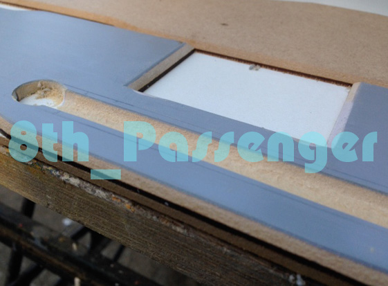
The pipe fits like this now.

Hopefully looks more the part.
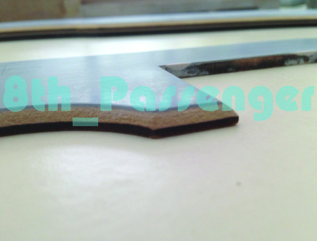
While I was set up routing I took a bit more off the edges of the side panels with the 45 degrees follow bit.

There's about a 1mm step up now before the chamfer. Subtle but I didn't want it going down to nothing.
Last Friday I had chance to make the basic metalwork for inside the body.

But later realised I'd cut the bottom steel flat too short... Doh!
Got a bit carried away and didn't think. Measure twice, cut once! So I need to get more steel and re cut and drill etc. The bit I cut wrong holds the rear tube in place so it has to be there.
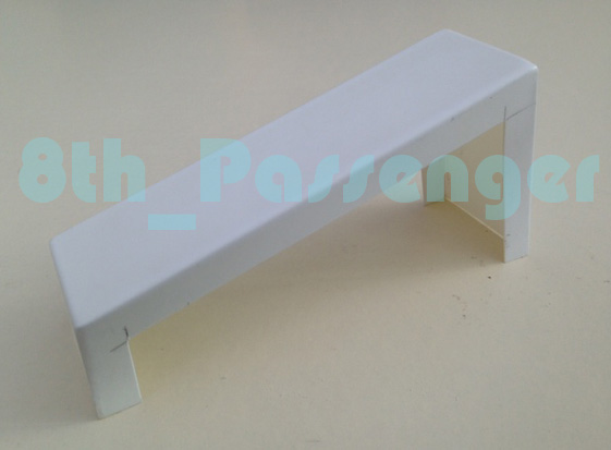
I also managed to have a go at vac-forming the forward vent casing. The seamless version!
I added some ABS to the sides of the former to create a void for the etched brass.
I had a small problem with webbing, due to the height of the former and size of the vacuum former.

But after a little gluing and trimming I got the shape I wanted out of it.
I marked out the etched brass sheet and cut it to size.

And loosely assembled them.

I'll have ago at the 'stepped' one next.
I'd also started blocking in some of the detail panels on the left side.
Unfortunately they warped a bit! I May glue them flat to board and mould them. Or start again. But I'd still mould them I think.
So here's what it's looking like now.
It's starting to get heavy!
Colin |
|
| Back to top |
|
|
|
|
|
|
|
|
|
|
|
| Author |
Message |
SKIN JOB 66
Community Member
Joined: 16 Jan 2008
Posts: 2724
Location: FRANCE
|
| Posted: Sun Sep 29, 2013 4:33 pm Post subject: |
|
|
GREAT update Colin, WOW !
I was thinking about the side pipe... It's a little weird to think they took the time to have it recessed into the body of the flamethrower... Why Bother ?
Now, if you consider it could have been a casted part glued to the side of the prop, because to make all the flamethrowers similar they had to use similar wiggets, or at least the more obvious of them... Then I would have personaly sanded the hidden part of the tube that was supposed to be glued to the body of the gun in order to improve its adherence... Sounds logical, don't you agree... and if you do so, then you'll probably end up with a tube that looks half recessed into the body of the gun !
Fred
PS : Please take another look at photo... the parallel lines and the spaces between them on the pipe (and the lower slim pipe as well), to me they don't look sharp enough, definitely the signature of a quickly made casting... Don't you agree ?
.jpg)
_________________
THE FUTURE IS A THING OF THE PAST |
|
| Back to top |
|
|
|
|
|
|
|
|
|
|
|
| Author |
Message |
SKIN JOB 66
Community Member
Joined: 16 Jan 2008
Posts: 2724
Location: FRANCE
|
| Posted: Sun Sep 29, 2013 4:45 pm Post subject: |
|
|
Oh, and GREAT work on the vent casting btw !
Fred
_________________
THE FUTURE IS A THING OF THE PAST |
|
| Back to top |
|
|
|
|
|
|
|
|
|
|
|
| Author |
Message |
SKIN JOB 66
Community Member
Joined: 16 Jan 2008
Posts: 2724
Location: FRANCE
|
| Posted: Sun Sep 29, 2013 5:05 pm Post subject: |
|
|
Just after I completed this post about the side tubes probably being castings I thought about something...
The flamethrowers were detailed by Martin Bower... Now, if you look at the main Nostromo model...
BINGO !
You can spot similar tubes on it ! I suppose they were castings and Bower simply took a few of them to detail the flamethrowers...

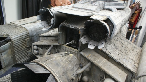
How can we have missed that all this time ? Evidences were just before our eyes...

Fred
_________________
THE FUTURE IS A THING OF THE PAST |
|
| Back to top |
|
|
|
|
|
|
|
|
|
|
|
| Author |
Message |
joberg
Community Member
Joined: 06 Oct 2008
Posts: 9447
|
| Posted: Sun Sep 29, 2013 7:59 pm Post subject: |
|
|
Great stuff on the vent, but like Fred I think that that pipe was cut a little more to get closer to the surface. And yes, those pipes are everywhere on the Nostromo
Keep up the good work Colin |
|
| Back to top |
|
|
|
|
|
|
|
|
|
|
|
| Author |
Message |
nickdaring
Community Member

Joined: 16 Dec 2006
Posts: 261
|
| Posted: Tue Oct 01, 2013 9:25 pm Post subject: |
|
|
Whoa! Nostromo pipes! How was that missed?!
Great eyes! |
|
| Back to top |
|
|
|
|
|
|
|
|
|
|
|
| Author |
Message |
joberg
Community Member
Joined: 06 Oct 2008
Posts: 9447
|
| Posted: Wed Oct 02, 2013 6:11 pm Post subject: |
|
|
As Fred has touched on the subject of casting and even with a silicone mold, that pipe would've been a pain in the rear end when de-molding it.
So, to keep the mold fairly intact, they opted for a recess option that we see on the original(s).
Btw Colin, that pipe is looking way closer to the original design than before |
|
| Back to top |
|
|
|
|
|
|
|
|
|
|
|
|
You cannot post new topics in this forum
You cannot reply to topics in this forum
You cannot edit your posts in this forum
You cannot delete your posts in this forum
You cannot vote in polls in this forum
|
|
|
|
|
|
|
|