|
 |
|
 |
|
| Author |
Message |
joberg
Community Member
.jpg)
Joined: 06 Oct 2008
Posts: 9447
|
 Posted: Fri Apr 07, 2017 8:19 am Post subject: Posted: Fri Apr 07, 2017 8:19 am Post subject: |
 |
|
Here's how it could be done (I'm no specialist in types of servos/motors available).

As you can see in my kick drawing, the rod would go through the housing at the top (of course) but also through the bottom of the machine.
You'd gain some room by cheating  since the rod will never be seen going under the prop. since the rod will never be seen going under the prop.
Also, to reduce the length of the push rod, you'll have to place it in a toward fashion (close to the attachment that's securing the bellows at the right hand side of the plan) rather than putting toward the end (left hand side).
You would still have room for the motor lifting the arm/eye combo (I hope it helps). |
|
| Back to top |
|
|
|
|
 |
|
 |
|
|
|
|
| Author |
Message |
Vader
Community Member

Joined: 19 Feb 2011
Posts: 267
Location: Sweden
|
| Posted: Tue Apr 11, 2017 5:07 am Post subject: |
|
|
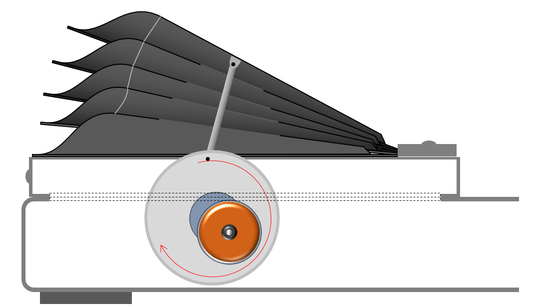
Surely the mechanically simplest way to implement the bellows mechanism must be just a rotating cam, something like the image below?
That way, you can just let the motor keep on going steadily in one direction, and the bellows will obligingly move up and down; the speed of the motion can easily be controlled through the speed of the DC motor.

_________________
26354 |
|
| Back to top |
|
|
|
|
|
|
|
|
|
|
|
| Author |
Message |
joberg
Community Member
Joined: 06 Oct 2008
Posts: 9447
|
| Posted: Tue Apr 11, 2017 7:07 am Post subject: |
|
|
Good one Vader  I didn't know that thing existed in the first place! I didn't know that thing existed in the first place!
Love it; it solves a lot of problems in terms of space for sure! |
|
| Back to top |
|
|
|
|
|
|
|
|
|
|
|
| Author |
Message |
Vader
Community Member
Joined: 19 Feb 2011
Posts: 267
Location: Sweden
|
| Posted: Tue Apr 11, 2017 8:12 am Post subject: |
|
|
I don't think it actually exists as such, but it's easy enough to make. Any circular disc of suitable diameter to act as a cam, and a fairly simple, off-the-shelf DC motor assembly (you have a ton of options here), and off you go.
That same place actually offers various fun options with linear servos and various other toys, but getting the same even movement you get with just a cam, a motor, a switch, and a battery using pretty much any other type of mechanism is a (a) a lot trickier and (b) more expensive. Reason why internal combustion engines still, 130-plus years later, use camshafts...
_________________
26354 |
|
| Back to top |
|
|
|
|
|
|
|
|
|
|
|
| Author |
Message |
Buch
Community Member

Joined: 27 Feb 2014
Posts: 1184
Location: Copenhagen, Denmark
|
| Posted: Tue Apr 11, 2017 8:44 am Post subject: |
|
|
That is pretty much the solution I've been playing with in my research for this beast.... couldn't you you just fix a rod to the perimeter of a rotation disc to push the bellows?
_________________
Monsieur, azonnal kövessen engem bitte |
|
| Back to top |
|
|
|
|
|
|
|
|
|
|
|
| Author |
Message |
Vader
Community Member
Joined: 19 Feb 2011
Posts: 267
Location: Sweden
|
| Posted: Tue Apr 11, 2017 9:25 am Post subject: |
|
|
You mean something like this image?
Sure, that would work, too. I just have a hunch making the disc rotate eccentrically and act directly on the bellows is simpler.
_________________
26354 |
|
| Back to top |
|
|
|
|
|
|
|
|
|
|
|
| Author |
Message |
Buch
Community Member
Joined: 27 Feb 2014
Posts: 1184
Location: Copenhagen, Denmark
|
| Posted: Tue Apr 11, 2017 10:05 am Post subject: |
|
|
That is the design I'm going to experiment with on mine... but I really like the idea with the cam!! Will the bellows own weight be enough to lower them after each turn?
_________________
Monsieur, azonnal kövessen engem bitte |
|
| Back to top |
|
|
|
|
|
|
|
|
|
|
|
| Author |
Message |
Vader
Community Member
Joined: 19 Feb 2011
Posts: 267
Location: Sweden
|
| Posted: Tue Apr 11, 2017 1:46 pm Post subject: |
|
|
It certainly should be. And even if it isn't, it's very easy to add a bit of weight to the inside of the uppermost "bellow".
_________________
26354 |
|
| Back to top |
|
|
|
|
|
|
|
|
|
|
|
| Author |
Message |
Buch
Community Member
Joined: 27 Feb 2014
Posts: 1184
Location: Copenhagen, Denmark
|
| Posted: Tue Apr 11, 2017 1:49 pm Post subject: |
|
|
Adding a bit weight wouldn't be a problem at all. So cool all of these design ideas are being shared!
_________________
Monsieur, azonnal kövessen engem bitte |
|
| Back to top |
|
|
|
|
|
|
|
|
|
|
|
| Author |
Message |
8th_Passenger
Community Member

Joined: 28 Nov 2009
Posts: 443
Location: Hertfordshire, UK
|
| Posted: Tue Apr 11, 2017 2:05 pm Post subject: |
|
|
A cam and linkage had been at the back of my mind Vader (Nicely illustrated).
As Buch pointed out in the other thread, the bellows with the block underneath is from the 'close ups' shot in the UK.
I have a feeling the block is there to contain the mech!
I did hear that it was done manually with rods under the table which wouldn't surprise me.
Colin
_________________
Ripley: What's it key on?
Ash: Micro changes in air density. |
|
| Back to top |
|
|
|
|
|
|
|
|
|
|
|
| Author |
Message |
LearnByMaking
Community Member

Joined: 31 Jan 2017
Posts: 63
Location: USA, Illinois
|
| Posted: Wed Apr 12, 2017 2:10 pm Post subject: |
|
|
I like the idea of the off center disc (reminds me of the vibration motors in some old game pads - motor with off center weight attached). I had thought of the disc with a rod attached like in combustion engines. Biggest issue seems to be how far the bellows need to move and if there is room to contain the mechanism (I haven't done the measurements yet).
Another possible mechanism is something like an auto scissor jack:
[img]http://6505at3mrb.weebly.com/uploads/1/9/7/2/19720361/6333149_orig.jpg?1369556094[/img]
In reply to Joberg, the stepper motor for the arm raise is 42mm high.
8th_Passenger's work looks amazing.
I got side tracked into putting together a mock up of the screen side (I think of it as the examiners side) for pretty much the same reasons that 8th_Passenger build up models of the smaller screens - I just needed to see the proportions, confirm measurements. etc. Mine is a bit cruder, just card stock and foam:
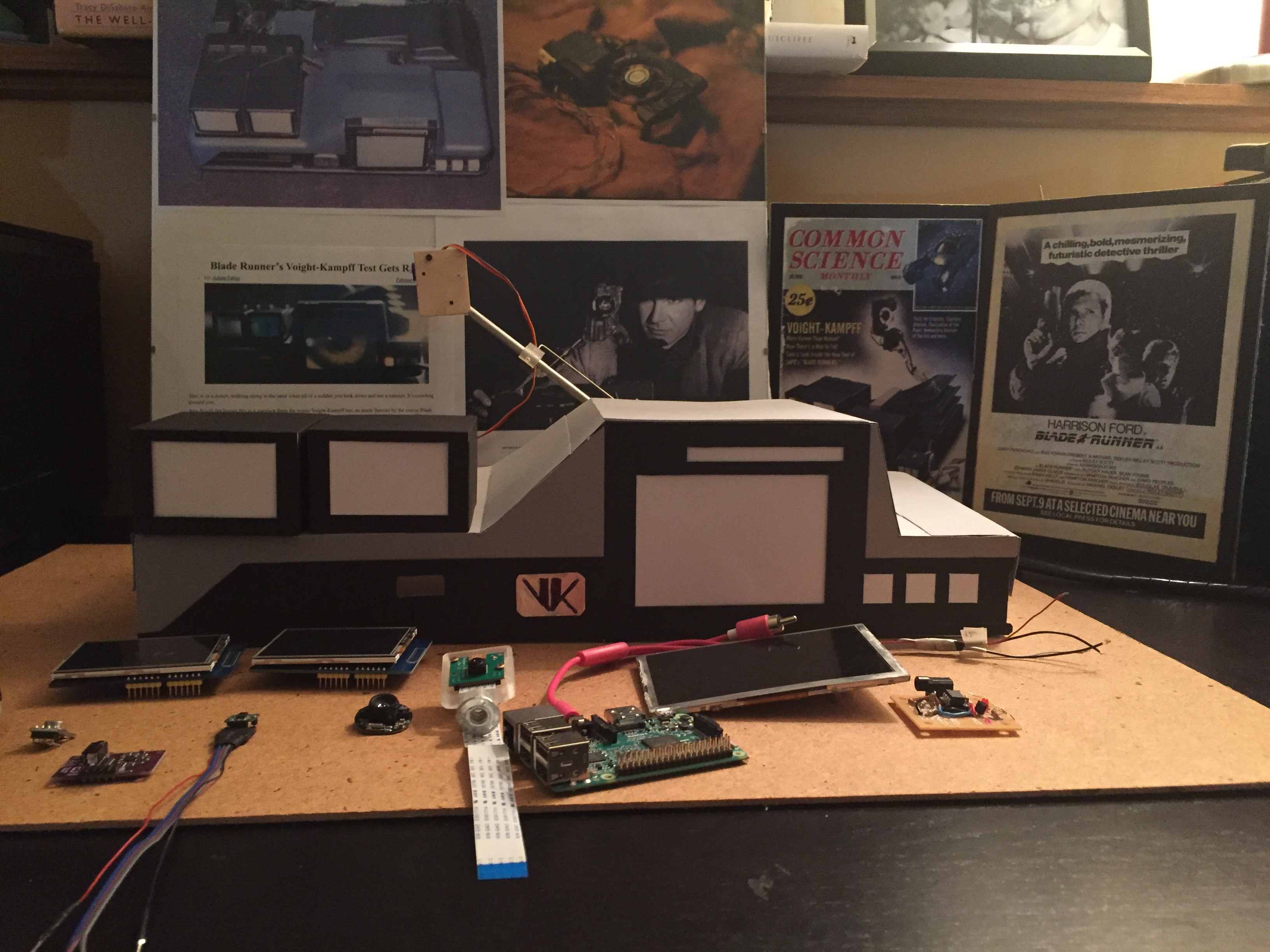
I'm also trying to build up a 3D CAD model like 8th_Passenger (his model seems quite a bit more developed ):

You can access my design files at https://cad.onshape.com/documents/cb7c199fecd1c9d080129028/w/ced4bad1bf548e19fb4c3765/e/a74888ee4c1af21c5230ee05 You may need to register for a free account but the files are publicly accessible.
_________________
If only you could see the things I've seen with your eyes. |
|
| Back to top |
|
|
|
|
|
|
|
|
|
|
|
| Author |
Message |
LearnByMaking
Community Member
Joined: 31 Jan 2017
Posts: 63
Location: USA, Illinois
|
| Posted: Wed Apr 12, 2017 2:26 pm Post subject: |
|
|
Sorry about the GIANT picture. I'll have to fix it tonight, after work.
_________________
If only you could see the things I've seen with your eyes. |
|
| Back to top |
|
|
|
|
|
|
|
|
|
|
|
| Author |
Message |
8th_Passenger
Community Member
Joined: 28 Nov 2009
Posts: 443
Location: Hertfordshire, UK
|
| Posted: Wed Apr 12, 2017 4:08 pm Post subject: |
|
|
Good progress LearnByMaking.
The size and proportions of your machine are dictated by the size of your monitors I guess.
I think you could make the bottom section a bit taller and don't forget the feet.
I'd try make the machine as narrow as you can. So I would redraw it a few times before you settle on a final size.
Colin
_________________
Ripley: What's it key on?
Ash: Micro changes in air density. |
|
| Back to top |
|
|
|
|
|
|
|
|
|
|
|
| Author |
Message |
joberg
Community Member
Joined: 06 Oct 2008
Posts: 9447
|
| Posted: Wed Apr 12, 2017 6:48 pm Post subject: |
|
|
| It's getting there...yes, a little bit higher for the sides (or face). It should be a little bit higher then half the big screen...if you see what I mean |
|
| Back to top |
|
|
|
|
|
|
|
|
|
|
|
| Author |
Message |
8th_Passenger
Community Member
Joined: 28 Nov 2009
Posts: 443
Location: Hertfordshire, UK
|
| Posted: Thu Apr 13, 2017 10:25 am Post subject: |
|
|
LearnByMaking Just had a quick look at your CAD stuff on the link you posted.
It's all looking great.
Will have a better look over the weekend.
Colin
_________________
Ripley: What's it key on?
Ash: Micro changes in air density. |
|
| Back to top |
|
|
|
|
|
|
|
|
|
|
|
| Author |
Message |
joberg
Community Member
Joined: 06 Oct 2008
Posts: 9447
|
| Posted: Thu Apr 13, 2017 10:59 am Post subject: |
|
|
| This is a fun project for sure... the more brains involved, the better |
|
| Back to top |
|
|
|
|
|
|
|
|
|
|
|
| Author |
Message |
LearnByMaking
Community Member
Joined: 31 Jan 2017
Posts: 63
Location: USA, Illinois
|
| Posted: Sun Apr 23, 2017 6:18 pm Post subject: |
|
|
Trying to re work measurements. What is the current consensus for the size of white buttons on the lower right (examiner side) on the VK (1.2, 1.5, 1.7)?
Working out bugs in my code for the arm raise, extension and rotation (adding magnetic end stops to trigger each stage).
Have some working prototypes of the LED bar graphs, both of them (above main screen and below smaller screens). A summary video of progress on this: https://youtu.be/tRoTafkjqy8
Dimensions for my current prototype for the LED bar graph above the main screen are: individual LED's 2x5mm, length of all 12 LED's together (including spacing) is 73.5mm. This is without the thin black and thicker white outline.
_________________
If only you could see the things I've seen with your eyes. |
|
| Back to top |
|
|
|
|
|
|
|
|
|
|
|
| Author |
Message |
LearnByMaking
Community Member
Joined: 31 Jan 2017
Posts: 63
Location: USA, Illinois
|
| Posted: Sun Apr 23, 2017 8:57 pm Post subject: |
|
|
Arrgh!!! Looking at 8th_Passengers thread at http://www.propsummit.com/viewtopic.php?t=5242&postdays=0&postorder=asc&start=20 and at my calculations using white buttons at 1.5cm (instead of 1.7cm - which I used before) I get a 415cm wide VK which makes the two LED bar graphs 32.1mm wide and 73.4mm wide. So I need to either space the LED's for the longer bar graph closer, or use different LED's and for the smaller bar graph I need a module just a bit larger (mine is 25.4mm wide). Well at least the circuit layout and code seems okay.
_________________
If only you could see the things I've seen with your eyes. |
|
| Back to top |
|
|
|
|
|
|
|
|
|
|
|
| Author |
Message |
LearnByMaking
Community Member
Joined: 31 Jan 2017
Posts: 63
Location: USA, Illinois
|
| Posted: Sun Apr 23, 2017 9:27 pm Post subject: |
|
|
Think I have a solution for the big LED bar graph, after looking for different sizes of rectangular LED's. Using 12 2x5 LED's gives a minimum of 60mm wide, adding 2.5mm space on each end - up to 65mm, add 1mm spacing between each LED is another 11mm so up to 76mm (just 2.6mm to long). Most of the structure of LED's is just housing, the sides can be sanded down to reduce there size (as long as you don't sand of the leads or cut into the lens or the tiny semiconductor chip). I've successfully done this with standard 5mm round LED's, now it's just a challenge to figure out the size and spacing to aim for!
Still need a substitute for the smaller bar graph - likely need to fabricate also.
_________________
If only you could see the things I've seen with your eyes. |
|
| Back to top |
|
|
|
|
|
|
|
|
|
|
|
| Author |
Message |
joberg
Community Member
Joined: 06 Oct 2008
Posts: 9447
|
| Posted: Mon Apr 24, 2017 6:35 am Post subject: |
|
|
I think that you have the solution for the long bar graph  |
|
| Back to top |
|
|
|
|
|
|
|
|
|
|
|
|
You cannot post new topics in this forum
You cannot reply to topics in this forum
You cannot edit your posts in this forum
You cannot delete your posts in this forum
You cannot vote in polls in this forum
|
|
|
|
|
|
|
|